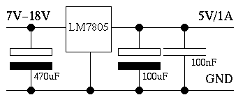
- 5V-Powersupply
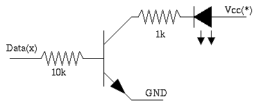
- 6 transistors: BC 547B (or other NPN)
- 6 resistors: 10k
- 6 resistors: 1k
- 6 LEDs: 2 red, 2 yellow, 2 green
- 1 Connector for the parallel port(25 or 36 pins).
Vcc has to be rather exactly 5 volts.(4.75-4.25) Higher voltages may damage your printer-port. The simplest way to get a 5-volt-source is to use a LM7805.


Transistor: Tested with BC 547B, but you can use any transistor with rather similar properies: NPN, Ic(max): 100mA, Uce(max):45V, P(max)=500mW, b:250-400
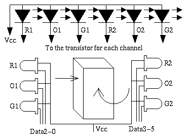
The circuit without the connector and the leds is so small, that you can put it into a matchbox. The simplest way to connect the LEDs is:

If you want to switch on only the first red Led R1, you have to send the value 1 to the printer. (Only the LSB=Data0 is set) If you send 6 to the printer, the O1 and the G1 Led is switched on...
traffic.zip contains a simple C-programm(dos) to simulate a traffic-light. You may also want to control the lights from java which is possible (with linux) using the PortTest application from project 7 (manual control) or the project 7 together with the TrafficLightAdapter from project 32.
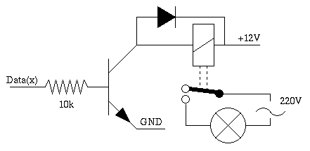
- You are able to control another circuit which isn't electically to your first circuit.
- You can control high voltages and/or currents such as electrical heaters or light bulbs.

Diode: 1N4148 U(max): 150V I(max)=100mA
Circuit can also be used for switch on/off the lights in your room/around your house, control the electrical heaters,...
Last updated: 15.07.2005